


RETROCOMPUTING
Homebrew computers come in a wide variety of forms, often dictated by their purpose and the particular (maybe peculiar) predilections of their creators. And two aspects that have a major effect on the computer's nature are the choice of inputs and outputs.
If your fascination with eight-bit micros revolves around video games, for example, then you'll certainly want video output, and sound would be a bonus. Also, you'll at least need a keyboard and maybe some joystick ports.
But I was never that fond of Jet Set Willy, Donkey Kong or Manic Miner (although there was a brief flirtation with Chuckie Egg). And I find the generation of video signals to be of only minor interest.
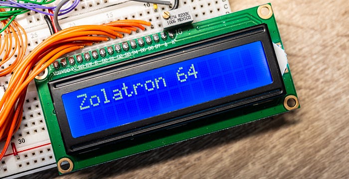
And so, when it came to input and output for the Zolatron 6502-based machine, I opted to keep it simple. Initial output was (and still is) to a simple character-based LCD panel (initially a 16 column by two line version, later upgraded to 20x4). And that would have been enough to satisfy my early curiosity. But there was still that problem of getting stuff into the machine.
Bit by bit
The obvious solution was a serial interface. I could then hook up the Zolatron via a cable to any other computer and use a terminal program to interact with it. Input and output in one connection.
Indeed, a serial interface was such a good idea that I ended up building two of them — and writing my own terminal program for the PC. This article will deal with the first successful attempt, and also hints at why I decided to follow it up with another.
Choosing a chip
In theory, adding a serial port isn't too difficult, involving little more than a single Universal Asynchronous Receiver-Transmitter (UART) chip.
Lots of people swear by their favourite UARTs, and popular options include the 6850 (designed for the 6800 family) and the NXP 2692A. But I made an early decision to go with the 6551. This is the chip designed for the 65xx architecture and so is (more or less) era-appropriate for the 65C02 CPU. It has a built-in baud rate generator and requires very little in the way of external components.
Of course, no-one makes it anymore. So I hit up eBay and availed myself of three pre-owned R6551 chips. Using eBay is always a gamble when buying chips: there are so many duds and fakes. But the ones that arrived had sensible date codes and looked the right vintage.
Uh-oh, we have a problem
Of course, then I found out there's a problem with the original NMOS version of the 6551. It has to do with an outgoing byte not being completely sent if the state of the CTS signal changes part way through.
This was fixed in the CMOS version of the chip. So back to eBay. I bought three 65C51 chips from a vendor in Poland. And while I was at it, I bought three WDC-branded chips, the W65C51, from a vendor in the UK, because what could possibly go wrong with genuine Western Design Center parts, right?
In fact, WDC still manufactures the W65C51, so I should probably have just ordered it from Mouser. But stay with me, because it was a fun journey.
Because that was when I learned that the WDC chips also have a bug — an even more serious one. The 6551 family has a status register and one of the bits in this register is the Transmit Data Register Empty (TDRE) flag. Basically, this is set to 1 if the previous byte that was in the register has been sent down the wire and it's okay for you to write another byte's worth of data to the Transmit Data Register. A typical software routine involves checking this bit, waiting until it goes high, then writing the byte. Simple.
Except that the bug in WDC's chip meant that this bit was always stuck high. And the firm never got around to fixing it. Instead, it published a workaround suggesting that you just put a delay loop in your code to give the chip time to send out the contents of the Transmit Register — which is a kludge if ever I saw one.
Allegedly, the Rockwell-branded chips don't have this problem. I ordered some from eBay, but they came from the usual vendors of sketchy parts so their provenance is obviously in some doubt.
Also, when the 'WDC' chips turned up, they were branded 'GT Eµ'. One way or another I ended up with nine Rockwell-branded 65C51 and the three, original R6551s (also Rockwell). Some of the chips have etching that looks suspiciously fresh.
Wiring it up
The pinout diagram for the 6551 somewhat belies my assertion that this is a simple chip to use. But once you break it down, it's not that tricky — at least for basic use.

The D0-D7 pins are the data bus, so no problem there. The PHI2, RWB, IRQB and RESB pins just connect to the identically named clock, read/write, interrupt request and reset pins on the 6502. And the TxD and RxD pins are our connection to the outside world. So what about the rest?
RS0 and RS1 deserve some attention. These are the register select pins. The registers are what you use to send and receive data and control or read the status of the ACIA. and they live at specific addresses—offset from whatever base address you've chosen for the ACIA. In my memory map, the decoding has the ACIA at address $B000. So that becomes the address of the first register.
Actually, precisely which register also depends on the state of the RWB (read/write) line. If you set the address to $B000 and RWB is low, then you're addressing the Write Transmit Data Register (whatever you have on the data bus will be written to this register). If RWB is high, then the Read Receiver Data Register operation is in play and whatever is in the read register gets put on the data bus. In this way, these three pins—RS0, RS1 and RWB give us control over eight possible operations. The addresses given in the following table are for my particular address map:
ADDRESS RS1   RS0   OPERATION RWB = LOW          OPERATION RWB = HIGH
------- ----  ----  ---------------------------- ---------------------------
$B000   Low   Low   Write Transmit Data Register  Read Receiver Data Register
$B001   Low   High  Programmed Reset             Read Status Register
$B002   High  Low   Write Command Register       Read Command Register
$B003   High  High  Write Control Register       Read Control Register
So, to carry out operations on this chip, I need to be able to set addresses $B000-$B003. To do this, RS0 and RS1 are connected to the address bus pins A0 and A1 respectively.
There are two chip select pins — CS0 and /CS1 (the latter being active low). I'm using decoding logic, so I tied CS0 high and /CS1 is connected to the relevant pin of the 74HC138 decoder.
One external component you do need is a 1.8432MHz clock crystal. This simply connects across the XTL0 and XTL1 pins. So no drama there.
The RTS and CTS pins are there if you want to do hardware flow control. I'm considering that to be optional for now. The same goes for DTR, DCD and DSR. The RTS and DTR pins are outputs, so I just ignored them. The other three I tied low (on the principle of never leaving inputs floating, especially with CMOS chips).
Just add code
Now all that was needed was some code.
Like I said, the ACIA lives at $B000 on my address map. So one of the things we do is define the addresses of its various registers, some of the settings we'll want to apply and some bit masks.
; ACIA addresses
ACIA_DATA_REG = $B000 ; transmit/receive data register
ACIA_STAT_REG = $B001 ; status register
ACIA_CMD_REG = $B002  ; command register
ACIA_CTRL_REG = $B003 ; control register

; Following are values for the control register, setting eight data bits,
; no parity, 1 stop bit and use of the internal baud rate generator
ACIA_8N1_2400 = %10011010
ACIA_8N1_9600 = %10011110
ACIA_8N1_19K2 = %10011111

; Value for the command register: No parity, echo normal, RTS low with no IRQ,
; IRQ enabled on receive, data terminal ready
ACIA_CMD_CFG = %00001011

; Mask values to be ANDed with status reg to check state of ACIA
ACIA_IRQ_SET = %10000000
ACIA_TX_RDY_BIT = %00010000
ACIA_RX_RDY_BIT = %00001000
We set up the ACIA:
; SETUP ACIA
  lda #0
  sta ACIA_STAT_REG   ; reset ACIA
  sta ACIA_INFO_REG   ; also zero-out info register
  lda #ACIA_8N1_9600  ; set control register config
  sta ACIA_CTRL_REG
  lda #ACIA_CMD_CFG   ; set command register config
  sta ACIA_CMD_REG
Towards the end of the code, I have a serial message defined. This ends with a line feed (ASCII 10) and then a null byte terminator:
.serial_msg
  equs "Zolatron 64 serial message"
  equb 10
  equb 0
And here's the routine that prints it to the serial port, which I implemented as a sub-routine because I intend to generalise it later. I'm using the X register as an offset counter, to determine which character in the message we want to send next. We pull that character into the Accumulator and then write that character to the data register. Because we're in write mode and are addressing that register, this has the effect of telling the ACIA to send the character. It's really that simple. We keep incrementing X until the character it pulls in is ASCII 0, at which point we're done.
.serial_msg_send
; SERIAL MESSAGE LOOP
  ldx #0                  ; set message offset to 0
.send_char
  lda serial_msg,x        ; load next char
  beq serial_send_end     ; if char is 0, we've finished
  jsr acia_wait_send_clr
  sta ACIA_DATA_REG
  inx
  jmp send_char
.serial_send_end
  rts
Not so fast
You'll note how this routine calls another subroutine, acia_wait_send_clr. This is meant to check that the previous character has been sent and the ACIA is clear to receive another incoming character. The subroutine waits until this is the case. And here's how I first implemented it:
.acia_wait_send_clr
  pha                   ; these five lines are how it should be done
  lda ACIA_STAT_REG
  and #ACIA_TX_RDY_BIT
  beq acia_wait_send_clr
  pla
The idea is that we load the ACIA's status register into A and AND it against a bit mask to check the state of the TX ready bit. If this produces zero, then we're not ready, so loop around again. There are two other important instructions — the initial PHA pushes the contents of the Accumulator on to the stack, to preserve its contents. At the end of the routine, we pull those contents back from the stack and into A. That way, we don't muck up anything important.
Study that bit of code. It contains a fatal error.
The main section of the code has an eternal loop that calls the routine to send the message, then delays for a brief moment, then does it all again, forever.
Huh? What now?
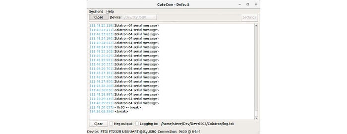
That's clearly not going to work. On the plus side, the message was appearing on the serial port, so something was working. I have the Zolatron hooked up to my electronics bench computer (a LattePanda Alpha) via an Adafruit FTDI Friend. With CuteCom running on the Alpha I could see the Zolatron valiantly attempting to communicate. But all I ever got was the first two characters of the message and then nothing. No looping.
Damn.
I suspected that one of the bugs present in various versions of the 6551, as discussed last time, might be the culprit. So I edited the .acia_wait_send_clr subroutine, replacing the check for the ready bit with just a very short loop. Basically, I put a value into the X register and then decremented it until it was zero.
That worked. Hmmm. It must be to do with those bugs, right?
I tried playing with different starting values for the X register, with the aim of reducing the delay to as short a time as possible. I'd started with $FF, which worked, so next I tried the opposite extreme and started with $01. That didn't work at all. So then I tried a mid-way point, $F0, and that worked. I was about to start working my way down when I spotted something in the .acia_wait_send_clr subroutine code — actually in the original version, which I'd simply commented out.
The fatal error I mentioned earlier jumped out at me. Every time the ready bit wasn't ready and I had to go around the loop again, I was including the instruction to push the Accumulator contents to the stack. But this is something that should have happened only once. I was probably overflowing the stack. Doh!
I got rid of the delay loop and changed the code to read like this:
.acia_wait_send_clr
  pha                      ; preserve A state on stack
.acia_wait_send_loop
  lda ACIA_STAT_REG        ; get the status register state
  and #ACIA_TX_RDY_BIT     ; compare with ready bit
  beq acia_wait_send_loop  ; if not set, loop
  pla                      ; recover state of A
  rts
Now there's only one push to the stack. The loop returns to a point just after this push.
The reason my delay loop version had worked is that I'd commented out the PHA and PLA. I didn't need them because the loop didn't use the Accumulator. This revised code worked!
Testing, testing
Okay. Now we have a working serial port, it's time to test all those 6551 chips I bought. To recap, I ended up with three kinds.
- R6551 chips, which have the CTS bug.
- R65C51 Rockwell chips, which are supposed to be okay.
- R65C51 Western Digital chips — at least, that's what the seller said they were, but when they turned up they were branded 'GT Eµ'.
The last one of those was what I had in the Zolatron when everything started working. So I was confident about that. The weird thing is, if it had been a genuine WDC chip, it shouldn't have worked. That's the version with the stuck-high ready to send bit in the Transmit Data Register. I'd already established that a ready-to-send routine that basically does nothing except wait for a very short time doesn't work. As the bit is stuck high with WDC chips, my current, working routine should always send without waiting, which I know doesn't work. So I'm pretty confident that these are not the WDC version of the CMOS chip. Maybe the GT chips are based on the Rockwell design?

The three original R6551 chips all worked. However, occasionally the computer would need a few resets before it jumped into action. I'm thinking this is to do with the CTS bug.
Of the 65C51 chips with the Rockwell logo, two worked. The Rockwell incarnation is supposed to be solid. Against all expectations, the chip with the very crisp lettering — I mean, it looked brand new — was one of the ones that worked. I'd assumed this had to be a re-lasered phony. It has a 1997 date code. But hey ho.
That left seven non-working chips. More investigation is needed to determine if they are simply dead or fakes, but that can wait for another day. I have five working CMOS chips and three original R6551s to play with.

Time to listen
So far we've only sent data out. And listening is so much harder than talking, don't you think?
That's how it turned out with the Zolatron's serial port, anyhow. Getting the computer to send messages was pretty easy. Receiving them? Not so much.
The first stages of developing the software were typical. I wrote code that I knew should work. It didn't. I cursed the binary gods for the fickleness of their logic until, at last, I saw the stupid mistake I'd made. Rinse and repeat.
It still didn't work.
Chucking the oscilloscope on the IRQ line showed me something that should have been obvious. The line was starting high after a reset, which is correct, and then going low after receiving the first character. Also correct. But then it was just staying low permanently.
So very wrong.
I needed a pull-up on the IRQ line. It turned out that I already knew this. My schematic for the Zolatron clearly shows a 3.3KΩ resistor pulling the IRQ line high. But I'd forgotten to implement this on the breadboard. Doh!
Adding that resistor certainly helped, but I was still having no joy in receiving short strings of text.
The code isn't that complex. When the 6551 ACIA receives a character, it triggers an interrupt. My interrupt service routine (ISR) puts the character into a receive buffer and also checks whether the character is a null byte (ASCII 0) or a carriage return (ASCII 13). If so, a flag is set at a memory location I'm using for registering the status of the serial port.
In the main loop of the program, I poll this register to see if that flag has been set. If so, the program prints whatever is in the receive buffer to the LCD display, and then clears the buffer.
As often happens, there were small, incremental improvements that suggested I was heading in the right direction. I used the LCD screen as part of the debugging — getting it to print certain characters to confirm that I was entering specific parts of the code, including the ISR. (And yes, I was.)
Totally munged
Eventually I got to the stage where, when sending a string, the first character would appear on the LCD okay, but all subsequent characters were corrupted. Totally munged.
That got me thinking. I added a test to the ISR to see if the overrun flag was being set. This gets set when data is arriving faster than the processor is processing it. And this turned out to be the case.
That's hardly surprising, perhaps, with a 6502 machine running at 1MHz using code that can hardly claim to be optimised.
I cranked down the baud rate from 9600 to 1200. Didn't help. (I've since turned it back up again.)
Within the ISR, I added a test near the end to see if the receive register of the ACIA is full. This register is only one character and so fills up quickly. I figured that I could continue pulling data from this register within the ISR — ie, the ISR could handle multiple characters instead of just one. If the processor didn't have to handle a separate interrupt for every character, it might be able to deal better with the rush. Here's the current ISR routine:
; ---------INTERRUPT SERVICE ROUTINE (ISR)--------------------------------------
.ISR_handler
  pha ; preserve CPU state on the stack
  txa
  pha
  ; Check which device caused the interrupt.
  bit ACIA_STAT_REG   ; if it was the ACIA that set IRQ low, the N flag is now set
  bmi acia_isr        ; branch if N flag set to 1
  ; do other checks here, branching as appropriate
  jmp exit_isr
.acia_isr
  ldx UART_RX_IDX          ; load the value of the buffer index
.acia_rx_get_char
  lda ACIA_DATA_REG        ; load the byte in the data register into A
  sta UART_RX_BUF,X        ; and store it in the buffer, at the offset
  beq acia_rx_set_null     ; if byte is the 0 terminator, go set the null flag
  cmp #13                  ; or is it a carriage return?
  bne acia_isr_end         ; if not 0 or CR, go to next step
  lda #0                   ; if it's a carriage return, replace the CR code
  sta UART_RX_BUF,X        ; we previously stored with a null
.acia_rx_set_null
  lda UART_STATUS_REG      ; load our status register
  ora #UART_FL_RX_NUL_RCVD ; set the null byte received flag
  sta UART_STATUS_REG      ; re-save the status
.acia_isr_end
  inx ; increment the index
  lda ACIA_STAT_REG        ; Load ACIA status reg - resets interrupt bit
  and #ACIA_RDRF_BIT       ; Is the Receive Data Register Full bit set?
  bne acia_rx_get_char     ; If so, we have more data
  jmp exit_isr
; there will be other stuff here one day, which is why we're jumping above
.exit_isr
  pla ; resume original register state
  tax
  pla
  rti
Getting worser all the time
That didn't help. In fact, things were getting worse. Sometimes I didn't see anything on the LCD. And the situation seemed to deteriorate with each new iteration of the code — to the point where, following a reset, the computer sometimes didn't send the init message via serial and often didn't even print the welcome message to the LCD. These were things that were sorted long ago. Why would they stop working too?
I stared at the code. It stared back at me. "This should work," I said. "But it doesn't," said the machine.
Then I rolled back to an earlier iteration of the code — a known-good state where the computer simply printed the welcome message on the LCD and continually sent out a simple message via serial.
It didn't work.
That was the Aha! moment. Maybe the problem wasn't software. Maybe it wasn't meatware. It could be the hardware.
I used the oscilloscope to probe around, checking that the clock signal was good, that the IRQ line was firing as expected, that there was stuff happening on the data and address lines. All that looked fine. And then I realised that my known-good program was suddenly working again. I'd clearly jiggled a wire somewhere during all that probing.
While doing all this, I also read an interesting thread on Reddit. This described the same situation I was seeing, with the first character being okay and others corrupted. One person suggested adding a delay between each character sent of, say, 10ms. This is easy enough to do in CuteCom (which I'm using on the Ubuntu-based lab computer).
I switched back to the latest version of the code, added that 10ms delay and… it worked!
Next steps
I was finding out, first hand, some of the limitations of working with breadboards. My mate Doug described the sight of my project as being like 'a cat's litter tray into which someone's dumped some old electronics'. He's not wrong. And so that was the moment I knew I had to summon my courage and lay out some PCBs.
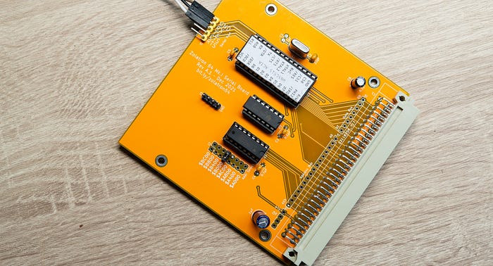
The picture above was my first attempt. It needed bodge wires. I don't want to talk about it.
I created a revised version of the board, which was much tidier. However, by this time, I was being attracted by the allure of another chip. While not so period-correct, it would give me the benefit of no known bugs and two serial ports. But that's for another day.

You can find all the stories related to this project on the Zolatron feature page.
There is also a GitHub Zolatron repo with the code, datasheets and other documents.
Steve Mansfield-Devine is a freelance writer, tech journalist and photographer. You can find photography portfolio at Zolachrome, buy his books and e-books, or follow him on Bluesky or Mastodon.
I'm also posting articles on Substack, where you'll find additional notes, updates, asides and general chit-chat. Subscribe there for the most complete experience.
You can buy Steve a coffee — it helps keep these projects going.